New Motorola APX XP Remote Microphone for Law Enforcement

The XP speaker-mics are discontinued. Our article, 2025 Motorola APX Remote Speaker-Mic Guide will provide the latest info for APX series.


Compatible with APX 7000, 6000, 4000, 3000, 1000, SRX 2200

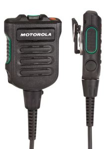
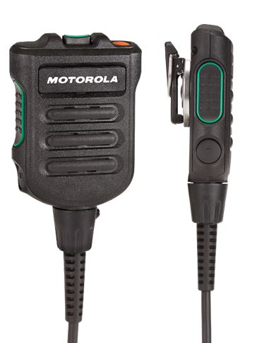
Motorola Solutions introduced a new thin remote speaker microphone designed for law enforcement, transit police, and ems personnel. The new IMPRES XP RSM uses dual microphone noise suppression technology like the XE RSM designed for firefighters. It is expected to start shipping in September.

Two Styles – IP68 Submersible or IP55 with 3.5mm Threaded JackNMN6271, NMN6274 XP RSM

The NMN6271 model has a Delta T submersible IP68 rating allowing it to survive under 2 meters of water for two hours. This microphone can be scrubbed with soap and water if needed.

Or…choose the NMN6274 with a IP55 rating that can handle a heavy rain storm and includes a 3.5mm threaded jack.

Both models include an orange emergency button, volume toggle, and one programmable button.

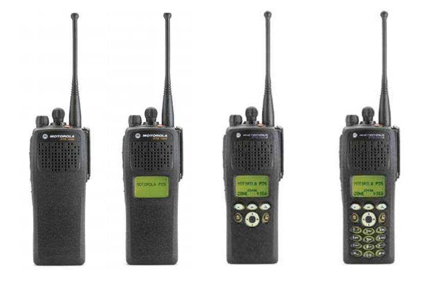
There are also 2 models on the roadmap for the Motorola XTS 5000, XTS 2500, and XTS 1500 due for release later this year.

Motorola Cancels ASTRO XTS 2500 and XTS 1500 Models

No More XTS Radio Orders After October 31, 2014XTS Model Cancellation

Motorola Solutions has published an intent-to-cancel notice for ASTRO 25 XTS 2500 and XTS 1500 radio models. The last day to order is 10/31/14 and requested ship dates are not permitted after November 30, 2014. No accessories are being cancelled and depot repair support will continue for 5 more years.

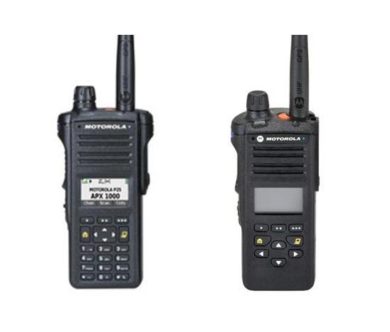
Popular APX Platform is the Recommended Replacement for XTS

APX P25 TDMA RadiosThe recommended replacements for the XTS 2500/1500 models include the APX 6000, 4000, and the new 1000 series.The P25 APX 4000 has a rugged XE version available and a new “2 knob” option will be available in the next few months. The APX 1000 also has P25 TDMA capability in a smaller form factor at a lower cost. For the largest selection of accessories please visit our APX online store for batteries, chargers, carrying cases, and audio enhancements.

New Long Range Wireless Speaker Microphone for APX and MOTOTRBO Mobile Radios

Works Up to 100 Meters from Your APX or XPR 4000/5000 Series Base/Mobile

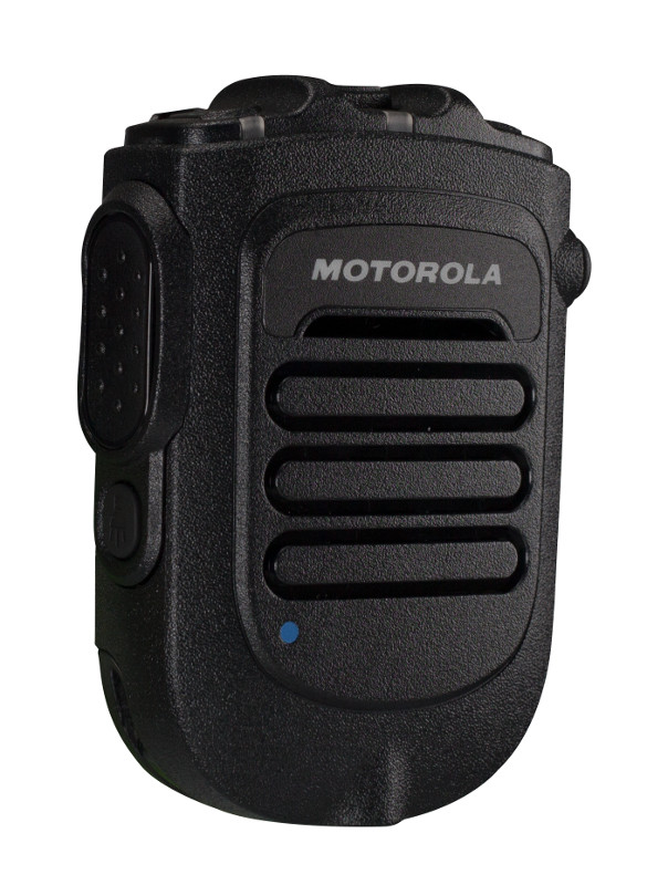
Motorola RLN6544 Wireless RSMMotorola Solutions introduced a new wireless remote speaker-microphone that will allow you to transmit and receive from your MOTOTRBO or APX mobile radio from up to 100 meters away.

The new RSM has a 3.5mm jack for receive-only audio accessories, a bright LED task light, and an 11 hour rechargeable battery. It can also transmit an emergency using the orange button on the top of the microphone.

Now you can use your high power APX, XPR 4000, or XPR 5000 series mobile radio when away from the vehicle or base.

Plug and Play Setup for Existing Vehicle or Base InstallationsWireless Gateway and Corded Mic

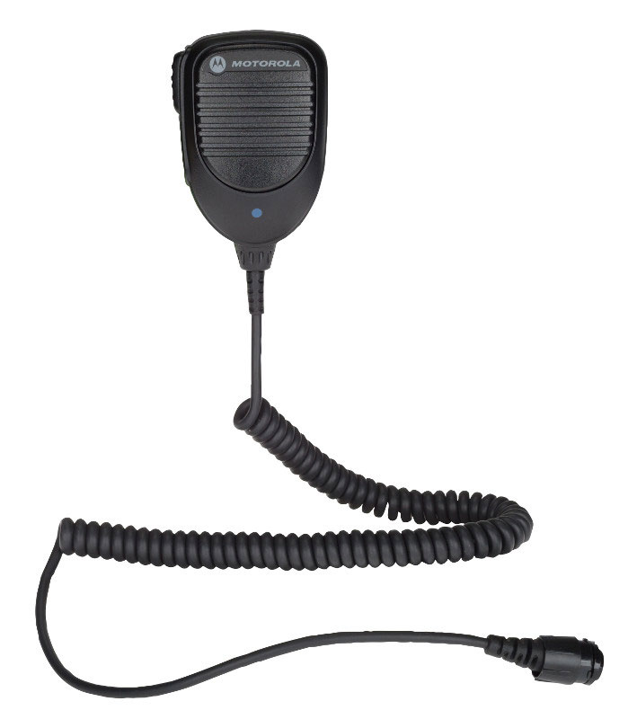
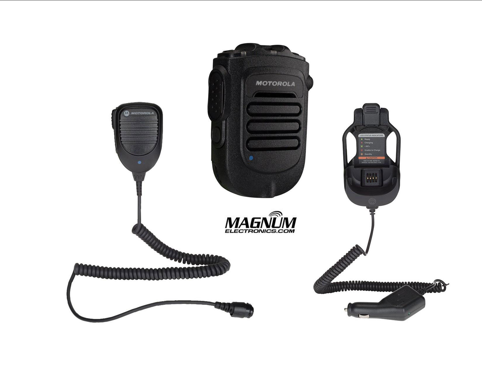
Adding to your existing MOTOTRBO or APX radio is easy. You will have to replace your existing mic with the Motorola PMMN4097 corded palm microphone with Bluetooth gateway. The RLN6544 wireless RSM uses touch pair to connect with the gateway and provides an audible announcement to confirm. The third component of the system is a charger. Choose the PMLN6716 12V DC charger with holder for a vehicle or the PMLN7120 AC desktop charger.

Wireless RSM Bundle Kits Available for Mobile or Base UseLong Range Wireless Speaker Mic

The RLN6551 long range wireless kit includes the RSM, gateway microphone and 12V DC charger for a vehicle. Our base bundle includes the RSM, gateway mic, and AC desktop charger. The RLN6552 kit includes the RSM and gateway without a charger.

For more info download the Motorola Long Range Wireless User Manual

The long range wireless solutions are compatible with the Mission Critical Wireless Pod software version R01.05.00 or later. APX mobiles must use R13.01 firmware or later that was released in April 2015.

How Magnum AVL Helps Business Owners with Fleet Management

GPS Fleet Tracking Without a Long Term Contract

Business owners and government agencies with small to mid-size fleets can experience the benefits of GPS vehicle tracking without a long term service contract. Our Magnum AVL Rental Program includes wired or OBD-II plug-in trackers and service plan with automatic updating. Track your vehicles using your desktop computer, tablet, or smartphone.

GPS Fleet Management Powered by Verizon Wireless

Magnum AVL fleet trackers utilize the Verizon Wireless nationwide network. Your vehicles, backhoes, and trailers are tracked using our cloud-based software using Google Maps with satellite, traffic, and street views. Our trackers have a backup battery and will send disconnect and reconnect alerts as well as continuous updates for up to an hour.

Email and text alerts are available based on location, posted speed, excessive idling, and harsh driving. Detailed, comprehensive management reports provide fleet data daily, weekly, and monthly.. 20+ reports can be automatically emailed, exported to a spreadsheet,  or saved in .pdf format.

We offer installation services, telephone support, and free training webinars. If you have a mobile workforce, Magnum AVL will impact your bottom line.

Contact us for a quote using the form below or call us at our Dover, Delaware headquarters at (302) 734-9250 M-F 8-5:00pm EST.


← Back

Thank you for your response. ✨


Motorola APX XTS Completely Discreet Wireless Covert Surveillance Accessories

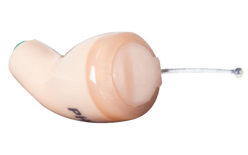
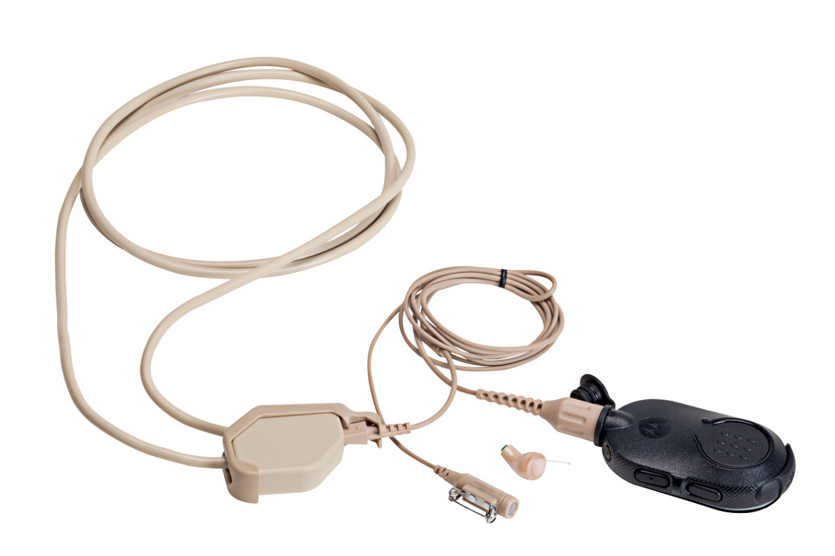
Wireless Covert Radio EarbudThe Motorola RLN4922 completely discreet earpiece is a covert wireless audio accessory inserted in the ear compatible with most two-way radios using a 2 or 3 wire surveillance kit. The earbud connector on the surveillance kit connects to the included RLN4920 wireless neckloop worn under your clothing. The push-to-talk switch and microphone on the wired surveillance accessory is still used. Recently, the RLN4922 was redesigned for more comfort, made smaller, and improved technically.

New Completely Discreet Mission Critical Wireless Covert Kit

Wireless enhanced Bluetooth Covert EarpieceUsers with the Motorola APX and enhanced Bluetooth option or XTS radios with the external PMLN5792 adapter have new options for covert surveillance. Motorola’s new NNTN8434 Wireless Covert Kit includes the RLN4922 wireless earbud, NNTN8385 Y-adapter, and NTN2571 PTT pod.

Now the radio can be placed in a backpack, briefcase, or purse up to 30 feet away. The NTN2571 PTT pod uses easy touch pairing. All you need to do is place the pod within an inch or two from the radio and it will automatically connect. Now a user can select any radio available and be ready for covert two-way communications immediately. The enhanced Bluetooth is encrypted and cannot be monitored like standard Bluetooth devices.

Basic Wireless Covert Kit Uses 2 Wire Earbud Headphones

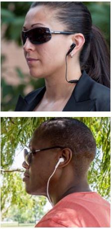
Person listening to music or using smartphoneAlso available is the NNTN8296 Basic Wireless Covert Kit that includes 3 sets of earbuds and a 3.5mm adapter for connecting any off-the-shelf commercial earphone accessory. Radio users appear to be using a smartphone or listening to music. 

The NTN2571 must be ordered separately. There is also an optional carrying case (RLN6485).

Typical battery life for the NTN2571 PTT pod is 8 hours but carrying a second pod will provide remote PTT and a spare power source for up to 16 hours of use. The pod uses a standard micro-USB charger.

For more information see the Motorola brochure APX and XTS Mission Critical Wireless Covert Solutions

The RLN4922 Completely Discreet Earpiece and wireless covert accessories are also available for MOTOTRBO Operations Critical Bluetooth. The NNTN8127 PTT pod is the operations critical wireless (OCW) version used with the NNTN8385 Y-adapter. You will also need to use the PMLN5712 or the PMLN5993 Bluetooth adapter with touch pairing for XPR 6000 series radios.


Light Indicators and How to Pair a Firecom Wireless Headset

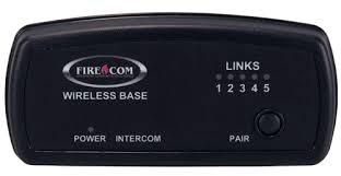
Firecom Wireless Headset LED Indicator and Audio Beep MeaningsFirecom Wireless Indicator Lights

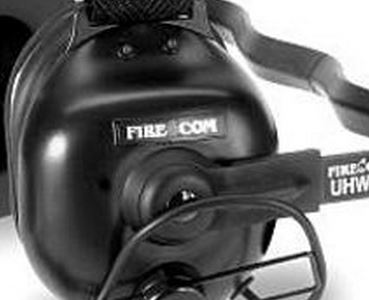
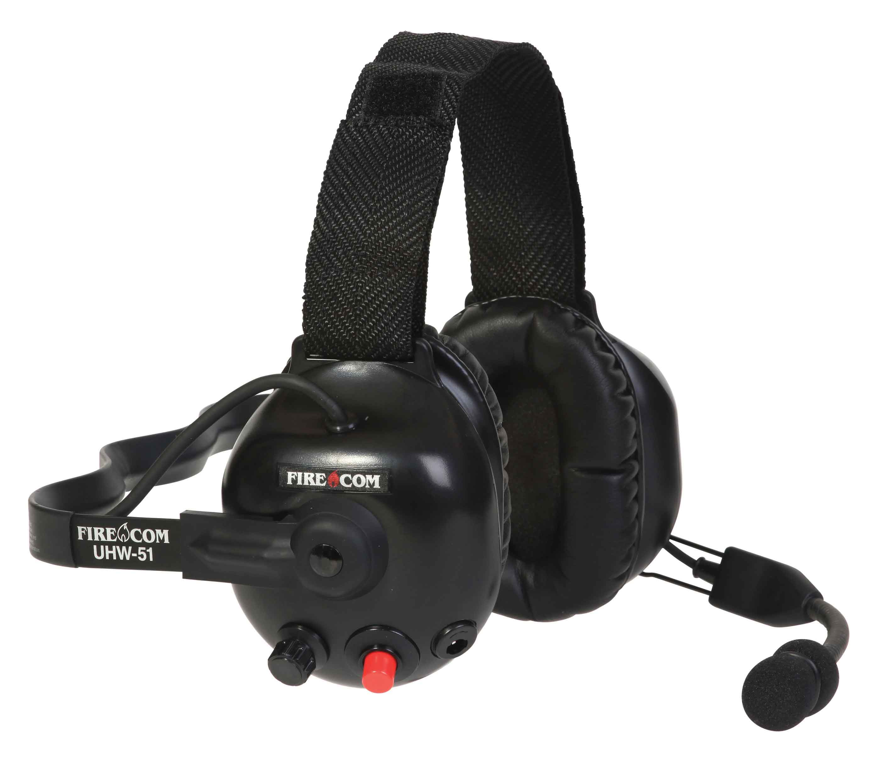
Firecom wireless headsets have one green and and one red LED indicator light on the top left ear dome (microphone side). The lights and audio beeps provide the user a quick indication if the headset is connected and the battery is charged.

Indicator Lights When Connected to Charger Cable

When the charger is plugged into the powered OFF headset it will show RED when charging and GREEN when fully charged. Charging takes 2 hours and will provide about 10 hours of normal operation.

When powered ON and charging, the light meanings are:

  • GREEN ON, RED ON: Charging, headset linked to base
  • GREEN ON, RED OFF: Charge complete, headset linked to base
  • GREEN Flashing, RED ON: Charging, headset not linked
  • GREEN Flashing, Red OFF: Charge complete, headset not linked

Indicator Lights When Charging Cable is Unplugged

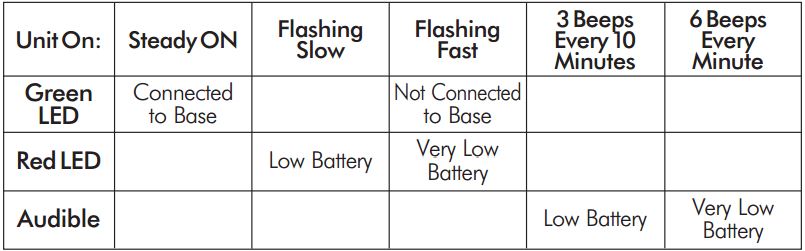
Below is a chart that shows what the light and beeps mean when the headset is powered ON and the charger disconnected:

Wireless Headset Indicator Light  ChartFirecom Wireless Headset Pairing Procedure & Video

Firecom Wireless BasePress and hold the pairing button on the base for approximately 6 seconds until the yellow LED(s) on the base station start flashing, indicating pairing mode. When placed in pairing mode, you have about 15 seconds to place the headset in pairing mode.

Firecom Wireless UHW-51 Press and hold the PTT button, turn on power to the headset. After approximately 5 seconds, the green and red LEDs on the outside of the left ear dome will start flashing in a relatively fast alternating pattern. Release the PTT button.

Monitor the headset lights. After about 6 seconds, the flashing pattern ends, the green LED will flash for two seconds and then the green and red LEDs will indicate the headset is paired and linked to the base. The LINK LED on the base will illuminate steadily after flashing rapidly for two seconds to indicate that a link to the headset has been established.

Motorola APX Mobile Control Head Choices Explained

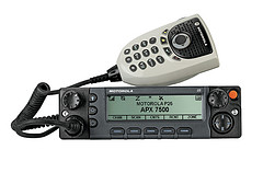
Configure Your APX With The Best Controls For Your InstallationMotorola APX 6500 O5 Head with Keypad Mic

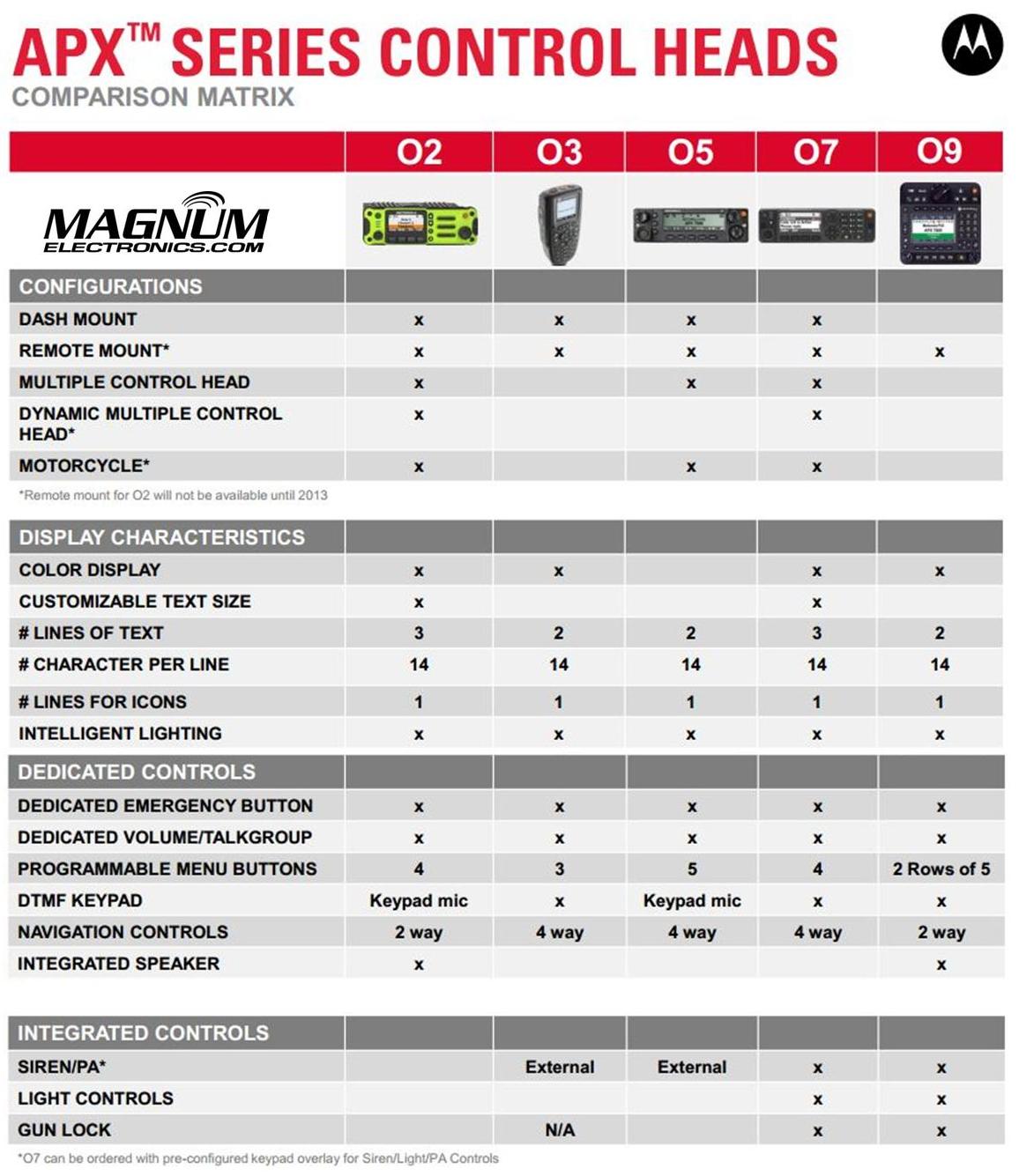
Until last year, only the O3, O5, and O9 heads were available for Motorola APX mission critical P25 mobile radios. The APX 4500 was introduced with the new O2 head for dash or remote mount configurations. There are now five control head choices available for the APX 6500 and APX 7500 radios including the O2, O3, O5, O7, and O9.

The O2 and O7 heads should be considered before you order your next APX 6500 or 7500.

APX O2, O3, O5, O7, O9 Control Head ChoicesChoose the APX O2 Head Option for Outdoor Installations 

The O2 head is rated IP55 for extreme environments and is designed for motorcycle, marine, and fire truck pump panel installations. We used this configuration for the South Bowers airboat. This rugged, XE style head has a color display, large knobs, and an integrated speaker.

Choose APX O7 Control Head for Integrated KeypadMotorola APX O7 Control Head

The O7 control head has a flush-mount design with integrated keypad, siren, lights, public address (PA) and gun-lock controls. It features a color display with enlarged multi-function rotary knob for easier control of talk-group and volume settings.

APX O5 and Specialized O3, O9 Control Heads Are Still Available

The O5 head is still the most popular option for most applications but the new choices make it a tougher decision. The O3 hand-held control head is perfect for covert and other special installations. The O9 head is packed with features but requires a bigger footprint.


Earmuff and Temple Headsets Compared

Radio Headset Comparison in High Noise

Bone Conduction vs.Traditional Earmuff Style in High Noise Areas

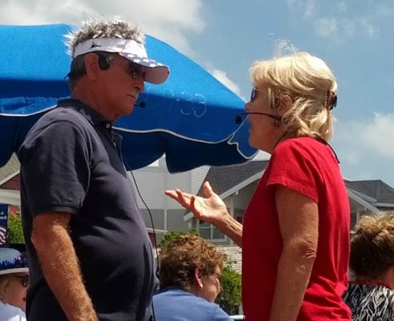
Motorola Solutions offers temple headsets for most two-way radio models and they continue to grow in popularity. Temple transducers use bone conduction technology and are more comfortable in hot weather as compared to traditional earmuff headsets.

Temple Headset Users TalkingTemple transducers keep the ears uncovered making it easier to communicate with the public. The speaker is muted so radio transmissions cannot be monitored and surrounding voices or other sounds can be heard normally. When used in high noise areas, earplugs can be worn for hearing protection.

Comparison Using MOTOTRBO Analog and Digital RadiosSpring and Associates HDD Driller

Spring & Associates, Inc an HDD (Horizontal Directional Drilling) contractor from Easton, Maryland relies on Motorola MOTOTRBO DMR digital radios on the jobsite.

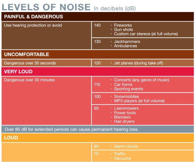
Communications are challenging because noise levels can be 100db and often exceed 130dB close to where the drill operator sits. They compared the Motorola PMLN5275 heavy-duty, dual muff headset and the PMLN5101 temple transducer.

Tests were performed in digital and analog modes using their XPR 6550 UHF two-way radios. Digital mode audio quality was found to be superior to analog. Following are comments by Rodney Spring, President  of Spring and Associates:

Muff Style Preferred in Extreme Noise Approaching 130dBLoud Noise Chart (dB)

In extreme noise, I’m guessing over 130dB, the earmuff headset was slightly preferred over the temple transducer/hearing protection muffs combo by the operator. It seems that when you idle up the drill to full power/full noise the muff headset has ZERO distortion in the receive mode, while the temple transducer has a little.

Temple Headsets Preferred Below 100dB Noise Level

In noise levels under 100dB the temple transducer was preferred because of comfort and during temporary times of low area noise, being able to remove the auxiliary hearing protection, and still be in touch with other radios while having the ability to hear people around him.

Over-the-Air Programming Steps for Motorola DTR Digital Radios

Written by Jeremy Byler, CETsr

How to Remotely Add or Update a DTR Radio Contact to your Fleet
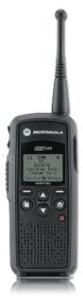
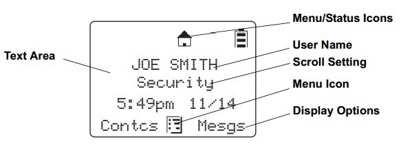
Motorola DTR650 License Free RadioMotorola DTR650 digital radios can be programmed with a unique ID so other users can identify the person transmitting. Most of our customers request that we program their radios with employee names or job functions. This is helpful during emergencies, call alerts, and one-to-one communications.Info Displayed on DTR
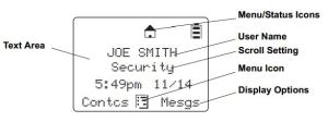
When an additional radio is purchased, replaced, or updated the digital ID must be programmed in all of the existing radios. This is easily accomplished using the DTR650’s over-the-air programming feature.

All DTR Radios Must Be Turned “ON” and In Range

After the new radio is programmed using Motorola’s DTR CPS software and programming cable, begin by inserting the battery and connecting the antenna. All radios must be powered ON and within range of the new DTR for programming to be successful.

Use Cloning Mode to Add Contacts Wirelessly

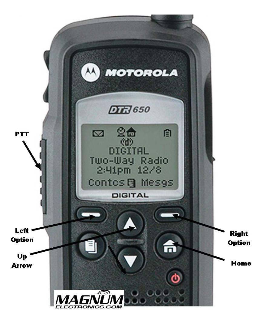
To place the new radio in cloning mode a series of button presses is required. Refer to the picture for button locations and follow the steps below:DTR Radio Button Labels
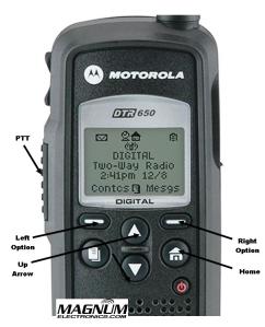
  • Hold down the “Home” button and press the PTT (push-to-talk) button three times
  • Press the “Left Option” button
  • Press the “Up Arrow” button
  • Press the “Right Option” button
  • Hold down the “Home” button and press the PTT button three times
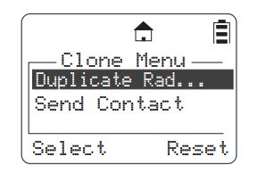
  • When done correctly screen will display cloning mode
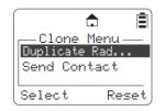
DTR Radio Cloning Menu Mode

From Cloning Menu Choose “Send Contact”

When the DTR is in cloning mode, scroll to the “Send Contact” and choose the contact you want to send to the other radios per steps 1-3 below.Steps 1-3 Adding DTR Contacts Remotely
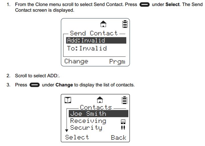
 Select the Contact You Want to Send to the Other DTR Radios

Steps 4-7 shows how to scroll through the list of radio contacts and change to the one you want to send to the other radios in your fleet.
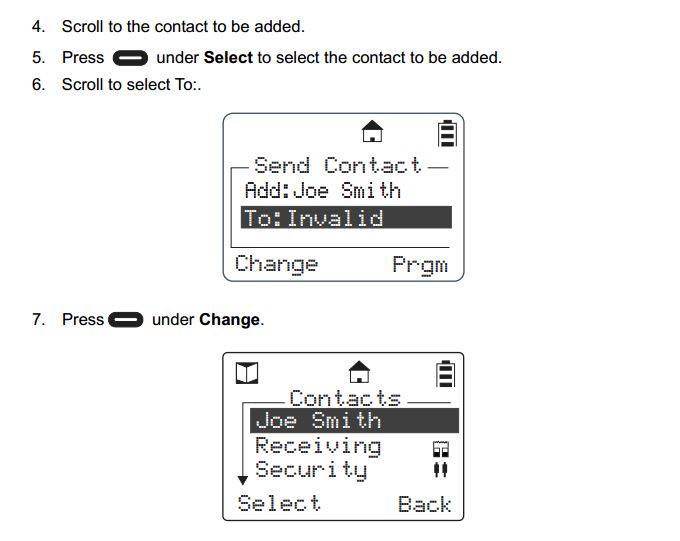
Steps 4-7 Add DTR Contacts Remotely

Press “Program” and “Go” to Finish the Cloning Operation

Steps 8-11 include selecting the target radio or radio group and sending the info wirelessly using the “Program” and “Go” soft buttons.
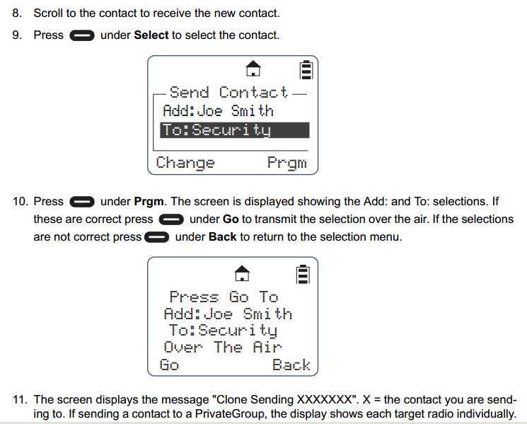
Steps 8-11 Add DTR Contacts Remotely

After operation is completed, a status message will appear. It will either display “Successful” or show a list of radios that failed. A radio will fail if it is powered off or is out of range.

If only a single radio needs to be updated, choose the name of the radio that needs to be updated instead of the group. Once this operation is successfully completed and all your radios have been updated with the new radio’s contact information, your DTR system will communicate properly.

For more information download the Motorola DTR Series User Guide and the Generation 3 DTR650 Product Training presentation from Motorola Solutions.
Motorola IMPRES Battery Tips and Charger Indicator Lights

Proper IMPRES Battery Care Starts With Initialization

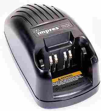
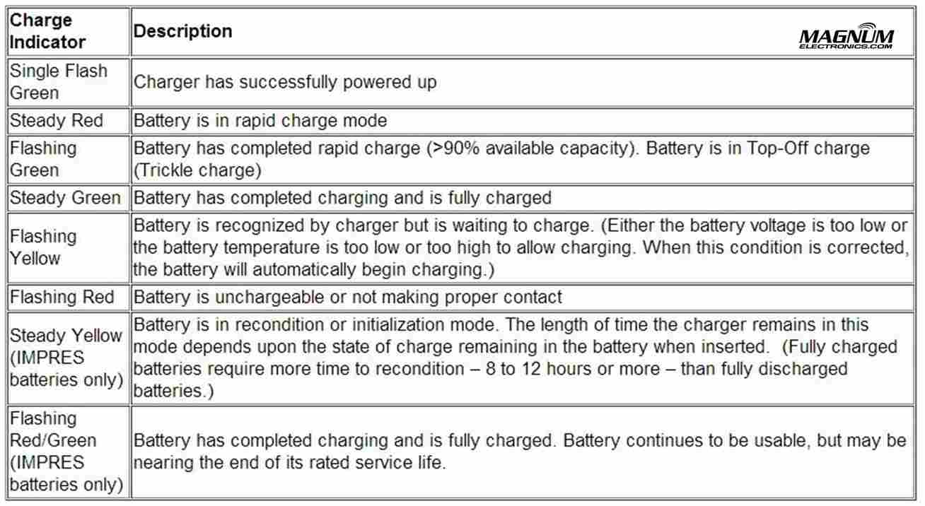
Motorola IMPRES ChargerA Motorola IMPRES battery must be initialized by an IMPRES charger the first time it is charged. This process is indicated by a STEADY YELLOW light on the charger indicator (the same as if the battery were reconditioning). The process is automatic, includes an initial reconditioning of the battery, and begins charging upon completion of this process.

This process requires approximately 12 hours depending on the capacity. Do not remove the battery from the charger until the STEADY GREEN light is on.

IMPRES Indicator Light Chart with Explanations

Motorola IMPRES Charger Light Indicators

IMPRES Automatic Battery Conditioning

Motorola IMPRES Adaptive Chargers, when used in conjunction with a Motorola IMPRES battery, have the ability to determine the appropriate time to recondition the battery. When an IMPRES battery is properly inserted into the charger, the charger determines if it is appropriate to recondition the battery. If the battery needs reconditioning, the charger automatically indicates a STEADY YELLOW.

This process may take up to 12 hours to complete, depending upon the state of charge and capacity rating of the battery when it is inserted. It is important to note, for this process to be effective, the IMPRES battery must be allowed to complete the recondition/recharge process. Leave the battery in the charger until the charger indicates a STEADY GREEN. At the completion of the recondition cycle, the charger automatically recharges the IMPRES battery.

How to Terminate the IMPRES Conditioning Process

At any time during the reconditioning process of a Motorola IMPRES battery (STEADY YELLOW indication), reconditioning may be terminated by removing and reinserting the battery back into the charger within 5 seconds. This causes the charger to terminate the reconditioning process and begin the charging process. The charger indicator changes to a STEADY RED. The charger will attempt to recondition the battery at the next battery insertion.

Manually Initiating the IMPRES Reconditioning Process

Within 2-1/2 minutes of the initial insertion of an IMPRES battery (STEADY RED indication), remove and reinsert the battery within 5 seconds to manually force reconditioning to occur. The charger indicator changes from a STEADY RED to a STEADY YELLOW. This forces the charger to recondition and automatically recharge the battery. This is a useful feature to have when IMPRES batteries have been in storage for several months or longer. Two or three manual recondition cycles may be required to rejuvenate the batteries, due to long term storage conditions.