Light Indicators and How to Pair a Firecom Wireless Headset

Firecom Wireless Headset LED Indicator and Audio Beep MeaningsFirecom Wireless Indicator Lights

Firecom wireless headsets have one green and and one red LED indicator light on the top left ear dome (microphone side). The lights and audio beeps provide the user a quick indication if the headset is connected and the battery is charged.

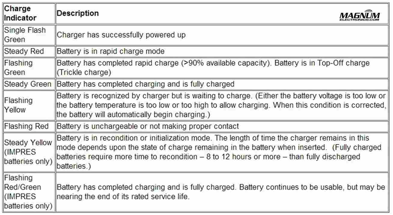
Indicator Lights When Connected to Charger Cable

When the charger is plugged into the powered OFF headset it will show RED when charging and GREEN when fully charged. Charging takes 2 hours and will provide about 10 hours of normal operation.

When powered ON and charging, the light meanings are:

  • GREEN ON, RED ON: Charging, headset linked to base
  • GREEN ON, RED OFF: Charge complete, headset linked to base
  • GREEN Flashing, RED ON: Charging, headset not linked
  • GREEN Flashing, Red OFF: Charge complete, headset not linked

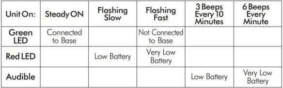
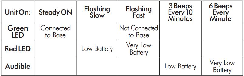
Indicator Lights When Charging Cable is Unplugged

Below is a chart that shows what the light and beeps mean when the headset is powered ON and the charger disconnected:

Wireless Headset Indicator Light  ChartFirecom Wireless Headset Pairing Procedure & Video

Firecom Wireless Base
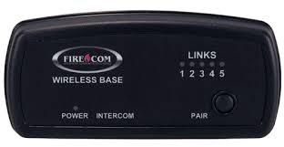
Press and hold the pairing button on the base for approximately 6 seconds until the yellow LED(s) on the base station start flashing, indicating pairing mode. When placed in pairing mode, you have about 15 seconds to place the headset in pairing mode.

Firecom Wireless UHW-51 
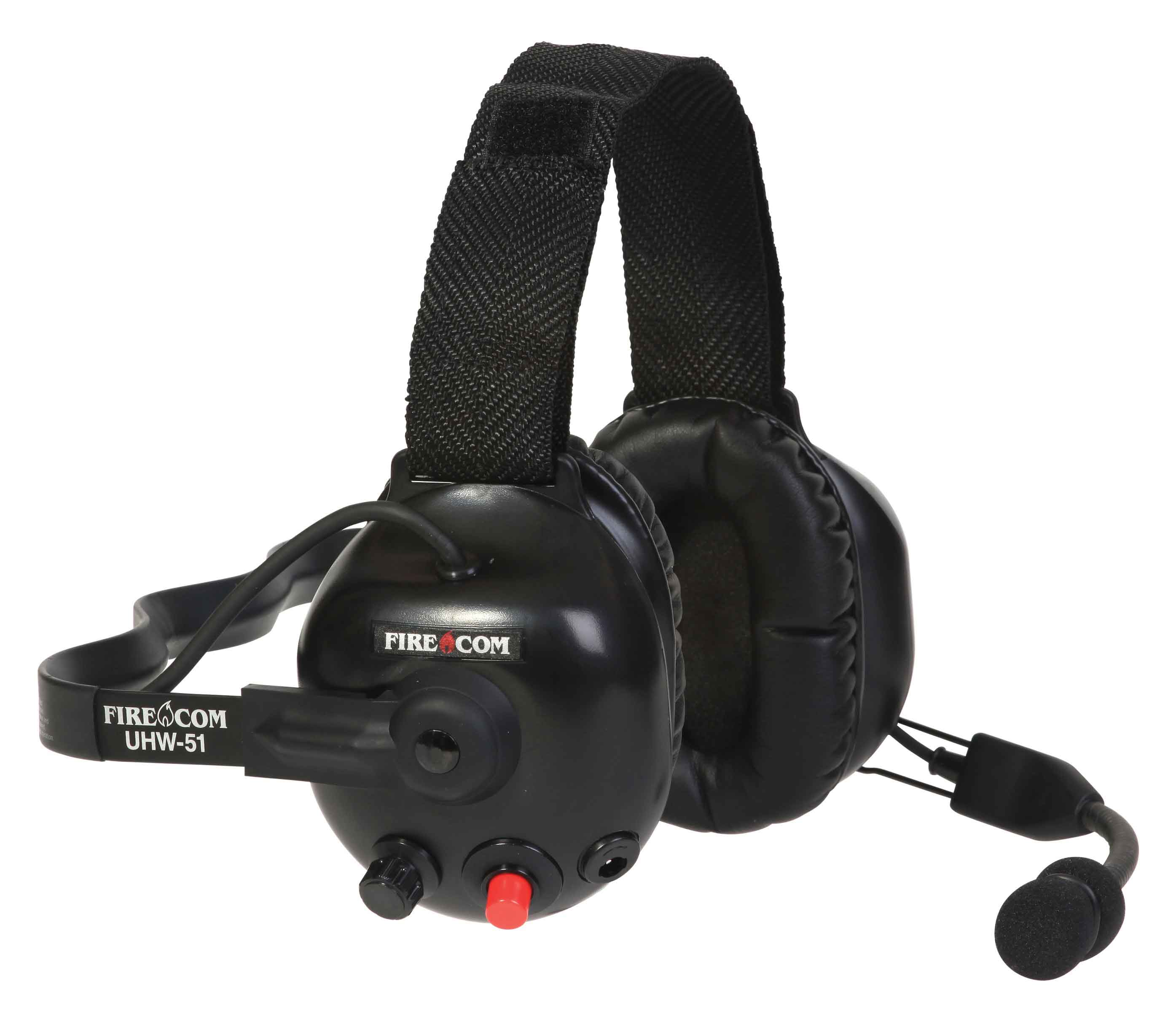
Press and hold the PTT button, turn on power to the headset. After approximately 5 seconds, the green and red LEDs on the outside of the left ear dome will start flashing in a relatively fast alternating pattern. Release the PTT button.

Monitor the headset lights. After about 6 seconds, the flashing pattern ends, the green LED will flash for two seconds and then the green and red LEDs will indicate the headset is paired and linked to the base. The LINK LED on the base will illuminate steadily after flashing rapidly for two seconds to indicate that a link to the headset has been established.

Motorola APX Mobile Control Head Choices Explained

Configure Your APX With The Best Controls For Your InstallationMotorola APX 6500 O5 Head with Keypad Mic

Until last year, only the O3, O5, and O9 heads were available for Motorola APX mission critical P25 mobile radios. The APX 4500 was introduced with the new O2 head for dash or remote mount configurations. There are now five control head choices available for the APX 6500 and APX 7500 radios including the O2, O3, O5, O7, and O9.

The O2 and O7 heads should be considered before you order your next APX 6500 or 7500.

APX O2, O3, O5, O7, O9 Control Head ChoicesChoose the APX O2 Head Option for Outdoor Installations 

The O2 head is rated IP55 for extreme environments and is designed for motorcycle, marine, and fire truck pump panel installations. We used this configuration for the South Bowers airboat. This rugged, XE style head has a color display, large knobs, and an integrated speaker.

Choose APX O7 Control Head for Integrated KeypadMotorola APX O7 Control Head

The O7 control head has a flush-mount design with integrated keypad, siren, lights, public address (PA) and gun-lock controls. It features a color display with enlarged multi-function rotary knob for easier control of talk-group and volume settings.

APX O5 and Specialized O3, O9 Control Heads Are Still Available

The O5 head is still the most popular option for most applications but the new choices make it a tougher decision. The O3 hand-held control head is perfect for covert and other special installations. The O9 head is packed with features but requires a bigger footprint.


Earmuff and Temple Headsets Compared

Radio Headset Comparison in High Noise

Bone Conduction vs.Traditional Earmuff Style in High Noise Areas

Motorola Solutions offers temple headsets for most two-way radio models and they continue to grow in popularity. Temple transducers use bone conduction technology and are more comfortable in hot weather as compared to traditional earmuff headsets.

Temple Headset Users TalkingTemple transducers keep the ears uncovered making it easier to communicate with the public. The speaker is muted so radio transmissions cannot be monitored and surrounding voices or other sounds can be heard normally. When used in high noise areas, earplugs can be worn for hearing protection.

Comparison Using MOTOTRBO Analog and Digital RadiosSpring and Associates HDD Driller

Spring & Associates, Inc an HDD (Horizontal Directional Drilling) contractor from Easton, Maryland relies on Motorola MOTOTRBO DMR digital radios on the jobsite.

Communications are challenging because noise levels can be 100db and often exceed 130dB close to where the drill operator sits. They compared the Motorola PMLN5275 heavy-duty, dual muff headset and the PMLN5101 temple transducer.

Tests were performed in digital and analog modes using their XPR 6550 UHF two-way radios. Digital mode audio quality was found to be superior to analog. Following are comments by Rodney Spring, President  of Spring and Associates:

Muff Style Preferred in Extreme Noise Approaching 130dBLoud Noise Chart (dB)

In extreme noise, I’m guessing over 130dB, the earmuff headset was slightly preferred over the temple transducer/hearing protection muffs combo by the operator. It seems that when you idle up the drill to full power/full noise the muff headset has ZERO distortion in the receive mode, while the temple transducer has a little.

Temple Headsets Preferred Below 100dB Noise Level

In noise levels under 100dB the temple transducer was preferred because of comfort and during temporary times of low area noise, being able to remove the auxiliary hearing protection, and still be in touch with other radios while having the ability to hear people around him.

Over-the-Air Programming Steps for Motorola DTR Digital Radios

Written by Jeremy Byler, CETsr

How to Remotely Add or Update a DTR Radio Contact to your Fleet

Motorola DTR650 License Free RadioMotorola DTR650 digital radios can be programmed with a unique ID so other users can identify the person transmitting. Most of our customers request that we program their radios with employee names or job functions. This is helpful during emergencies, call alerts, and one-to-one communications.Info Displayed on DTR

When an additional radio is purchased, replaced, or updated the digital ID must be programmed in all of the existing radios. This is easily accomplished using the DTR650’s over-the-air programming feature.

All DTR Radios Must Be Turned “ON” and In Range

After the new radio is programmed using Motorola’s DTR CPS software and programming cable, begin by inserting the battery and connecting the antenna. All radios must be powered ON and within range of the new DTR for programming to be successful.

Use Cloning Mode to Add Contacts Wirelessly

To place the new radio in cloning mode a series of button presses is required. Refer to the picture for button locations and follow the steps below:DTR Radio Button Labels

  • Hold down the “Home” button and press the PTT (push-to-talk) button three times
  • Press the “Left Option” button
  • Press the “Up Arrow” button
  • Press the “Right Option” button
  • Hold down the “Home” button and press the PTT button three times
  • When done correctly screen will display cloning mode

DTR Radio Cloning Menu Mode

From Cloning Menu Choose “Send Contact”

When the DTR is in cloning mode, scroll to the “Send Contact” and choose the contact you want to send to the other radios per steps 1-3 below.Steps 1-3 Adding DTR Contacts Remotely

 Select the Contact You Want to Send to the Other DTR Radios

Steps 4-7 shows how to scroll through the list of radio contacts and change to the one you want to send to the other radios in your fleet.

Steps 4-7 Add DTR Contacts Remotely

Press “Program” and “Go” to Finish the Cloning Operation

Steps 8-11 include selecting the target radio or radio group and sending the info wirelessly using the “Program” and “Go” soft buttons.

Steps 8-11 Add DTR Contacts Remotely

After operation is completed, a status message will appear. It will either display “Successful” or show a list of radios that failed. A radio will fail if it is powered off or is out of range.

If only a single radio needs to be updated, choose the name of the radio that needs to be updated instead of the group. Once this operation is successfully completed and all your radios have been updated with the new radio’s contact information, your DTR system will communicate properly.

For more information download the Motorola DTR Series User Guide and the Generation 3 DTR650 Product Training presentation from Motorola Solutions.

Firefighter Training Video – “Say It Loud and Clear”

Video

Best Practices Developed by Motorola and the IAFC

Motorola BatwingsMotorola and the International Association of Fire Chiefs (IAFC) developed a 15 minute training video to review best practices when using mission-critical 2-way radios for fireground operations. The training applies to all radio brands and models.

IAFC SealThe video shows typical scenarios how a firefighter can minimize background noise and maximize voice communications intelligibility. Whether you use analog, digital, 800 MHz, or VHF/UHF – the tips to improve audio quality all apply.

Rehoboth Beach Patrol Upgrades Lifeguard Communications

Rehoboth Beach, DE

Thousands of visitors pack the narrow strip of sand at Rehoboth Beach each summer resulting in hundreds of urgent events including lost children, water rescues, and medical emergencies. Rehoboth Beach Patrol, led by Captain Kent Buckson, has been the first responder team for the resort since 1921.

Rehoboth Beach Patrol LogoNot that long ago, most beach patrols relied on semaphore flags for mission-critical communications. The visual messages took several minutes to “transmit” vital information along the entire beach. Analog 2-way radios improved communications but still lacked features required for public-safety.

Starting Memorial Day Weekend, Rehoboth Beach Patrol will improve their Motorola MOTOTRBO DMR XPR 6550 digital radio coverage by adding  a XPR 8400 repeater located on top of the City’s water tank. This will provide better radio-to-radio communications especially during emergencies.

Submersible MOTOTRBO Digital 2-Way Radios Improve Beach Safety

Motorola XPR 6550Motorola MOTOTRBO digital XPR 6550 hand-held radios are rugged enough to provide reliable communications from each lifeguard stand along the crowded shoreline. The XPR 6550 carries a IP57 submersible rating that protects the internal electronics from the harmful effects of sand and salt water. A bright orange silicone grip case provides additional protection and makes it easier to locate if dropped in the sand or surf.

Internal text based information from Headquarters is received on the XPR 6550’s rugged screen reducing the need for voice communications. A press of the orange button alerts the team when an emergency occurs. The radio is programmed with an identifier that provides precise location information when backup is needed.

Our Magnum Electronics team is proud to have been given the opportunity to design, install, and provide ongoing support for their next generation communications system that enhances public-safety on the beach.

Motorola Announces XTS 5000 and XTL 5000 P25 Radio Cancellation

Last day to order XTS5000 is 10-31-13Motorola made it official today with their cancellationXTL5000 Last day to order 10-31-13 announcement of the XTS 5000 and XTL 5000 P25 radios. The last day to order is October 31, 2013.

XTS and XTL accessories will continue to be available with depot repair support until the end of 2018.

New and Improved APX P25 Radios are the Replacements for XTS/XTL

New APX P25 Portables are the replacement for XTS XTL radiosThe APX platform has been shipping for about 2 years slowing XTS/XTL shipments. Public-safety agencies prefer the new APX P25 radios because of their durability, audio quality, and advanced features.

A full complement of audio and charging accessories are available.

Motorola Trade-in Promo Reduces APX price up to $450

Motorola has a $450 trade-in offer in effect until June 26, 2013 if you purchase a new APX. This discount is in addition to any special contract pricing. For details call your authorized Motorola manufacturer’s representative.

Motorola IMPRES Battery Tips and Charger Indicator Lights

Proper IMPRES Battery Care Starts With Initialization

Motorola IMPRES ChargerA Motorola IMPRES battery must be initialized by an IMPRES charger the first time it is charged. This process is indicated by a STEADY YELLOW light on the charger indicator (the same as if the battery were reconditioning). The process is automatic, includes an initial reconditioning of the battery, and begins charging upon completion of this process.

This process requires approximately 12 hours depending on the capacity. Do not remove the battery from the charger until the STEADY GREEN light is on.

IMPRES Indicator Light Chart with Explanations

Motorola IMPRES Charger Light Indicators

IMPRES Automatic Battery Conditioning

Motorola IMPRES Adaptive Chargers, when used in conjunction with a Motorola IMPRES battery, have the ability to determine the appropriate time to recondition the battery. When an IMPRES battery is properly inserted into the charger, the charger determines if it is appropriate to recondition the battery. If the battery needs reconditioning, the charger automatically indicates a STEADY YELLOW.

This process may take up to 12 hours to complete, depending upon the state of charge and capacity rating of the battery when it is inserted. It is important to note, for this process to be effective, the IMPRES battery must be allowed to complete the recondition/recharge process. Leave the battery in the charger until the charger indicates a STEADY GREEN. At the completion of the recondition cycle, the charger automatically recharges the IMPRES battery.

How to Terminate the IMPRES Conditioning Process

At any time during the reconditioning process of a Motorola IMPRES battery (STEADY YELLOW indication), reconditioning may be terminated by removing and reinserting the battery back into the charger within 5 seconds. This causes the charger to terminate the reconditioning process and begin the charging process. The charger indicator changes to a STEADY RED. The charger will attempt to recondition the battery at the next battery insertion.

Manually Initiating the IMPRES Reconditioning Process

Within 2-1/2 minutes of the initial insertion of an IMPRES battery (STEADY RED indication), remove and reinsert the battery within 5 seconds to manually force reconditioning to occur. The charger indicator changes from a STEADY RED to a STEADY YELLOW. This forces the charger to recondition and automatically recharge the battery. This is a useful feature to have when IMPRES batteries have been in storage for several months or longer. Two or three manual recondition cycles may be required to rejuvenate the batteries, due to long term storage conditions.

Complete List of Motorola KVL Encryption Keyload Cables and Adapters

Motorola KVL 3000 and 4000 Cables

KVL 3000/4000 Keyload Interface Cables and Adapters

Most Motorola military and law enforcement 2-way radio communications uses an encrypted algorithm for secure voice messages. The encryption key is inserted in the radio using a KVL 3000 or KVL 4000 as shown. The basic interface cable is the Motorola TKN8531 and an adapter specific to the radio model. XTS 5000/2500 series portable hand-held radios require a NTN8613 adapter. APX 7500/6500  and most XTL 5000/2500 mobile radios need the HKN6182.

APX 7000/6000 series use the WPLN6904 cable that does not require an adapter.

OTAR and Radio Authentication Cables 

For systems using OTAR (over-the-air-rekeying) or radio authentication, the KVL uses a different set of cables without the need for adapters. APX, XTL, and Astro Spectra mobile radios use the HKN6183. XTS portable radios require the RKN4106 and APX 7000/6000 portables use the WPLN6905 cable.

For a complete list of KVL 4000 cables, adapters, and accessories, see the charts below.

Motorola KVL Interface Cables and Adapters

Optional accessories for the KVL 4000:

KVL Optional Accessories

Vertex Standard VX-350 Series Cloning Procedure

Vertex VX-350 Series Cloning Steps

Vertex VX-351 or VX-354 Cloning Requires a CT-27A Radio-to-Radio Cable

Adding a new Vertex Standard VX-351 or VX-354 radios to your existing fleet is a simple process with the built-in cloning feature. All you need is a Vertex XURTS0008 CT-27A cloning cable  to transfer the programming information. A VX-351 will not clone to a VX-354 and all models must be identical using the same VHF or UHF band.

VX-350 Series Cloning is a 6 Step Procedure

  1. Turn both radios OFFVertex 350 Buttons and Controls
  2. Connect the CT-27 cloning cable between the MIC/SP jacks of the two radios.
  3. Press and hold the “Side 1” key and the “PTT” key while turning the radio ON.  The LED will remain off and if a VX-354, it will display “CLONE”.
  4. Repeat step 3 on the other radio.
  5. To switch the radio to receive data, press the “Side 1” key. Then the LED indicator will glow “Green“.
  6. To switch the radio to transmit data, press the “PTT” key. Then the LED indicator will glow “Red“.

When the data transfer is successful, the VX-354 display will return to “CLONE” or if a VX-351, the TX/BUSY indicator will turn off. You are now ready for the next radio or turn both radios off and disconnect the CT-27 cable. You can then power on the radios and begin normal operation.